Large Area Hearing Loop Systems (Design & Installation)
Engineered hearing loop coverage for houses of worship, auditoriums, theatres, courtrooms and large public spaces.
What is a Large Area Hearing Loop?
An Area (or Large Area) Hearing Loop is a permanently installed system that transmits clear audio directly to compatible hearing aids and cochlear implants.
It’s best suited to audio-led venues with fixed seating, where distance from speakers and room echo can reduce clarity for listeners. The first step to installation is a site survey to confirm feasibility, loop design, and expected performance.
Access to hearing loops is essential in these environments. Many venue types fall into this category; below are some of the most common.
Prefer to speak directly? Call 727-260-3488
Typical Areas of Extended Use
Theatres, Cinemas, And Performing Arts Facilities
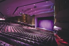
Van Wezel Performing Arts Hall
High School and College Auditoriums and Classrooms
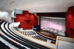
North Port High School
Houses of Worship - Sanctuaries, Fellowship Halls, and Worship Centers

Epiphany Cathedral (Venice)
Government Chambers and Libraries

Gainesville City Council
Sports Arenas and Stadiums

Breslin Arena at Michigan State
Airport Terminals
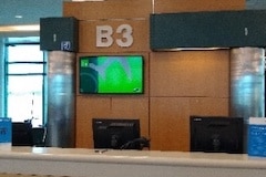
Sarasota Bradenton Airport
Other Areas:
Board Rooms
Meeting Rooms
Banquet Facilities
Funeral Homes
Sports Arenas
Council Chambers
Buses
Club Houses
Trams
Trains
Cruise Ships
Each venue has unique characteristics that require a custom design to ensure the Loop System performs correctly after the install is completed. In order to engineer and design the system properly, a site visit is required. At that site visit, a test Loop will be used.
Testing
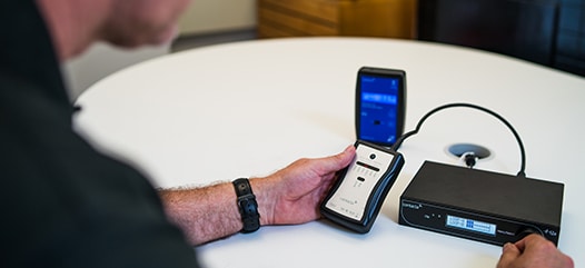
The test Loop involves:
- Laying wire down on the floor, sending some tones and noise through the system, and taking output readings.
- We test for:
- Electrical interference (EMI)
- Signal strength and evenness
- Frequency response
- Metal loss.
Electrical interference
- Manifests itself as a buzz or hum that can generally only be heard in a Loop Receiver or t-coil equipped hearing instrument. It is not usually heard by the naked ear but on occasion it is possible.
- Most EMI can be resolved by us working with an electrician or power company and doing some basic troubleshooting. However, there are times where the issue is so great that the space is no longer a candidate for a Loop.
- Many times, poor grounding or incorrect electrical wiring is the culprit.
Metal loss
- Occurs when there is excessive metal used in the construction of floor or ceiling.
- Often occurs in the second story/floor and up, although it can occur on the ground floor as well.
- Metal loss can cause a weak to no signal to occur, loss of high frequency sound, and uneven signal distribution throughout the room.
Design

Functional designs are achieved by utilizing the test results and incorporating basic and advanced fundamentals of Looping.
- Even Signal – In engineering a design, it important that even signal distribution throughout the room is obtained. This ensures that regardless of where a person sits from event to event, that the volume is relatively the same each time.
- Frequency response – Is critical for providing the clearest speech possible which ensures the users has the best chance possible at understanding what they are there to hear. A relatively flat frequency response is of the highest priority.
There are some basic types of Loop designs ranging from:
- Perimeter Loop
- Multiple Loop Arrays – Figure 8 (2 Loop array) and Snowman
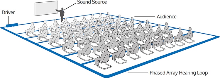
- Phased Array
It is preferable, where possible, to use the most advanced design possible like the Phased Array. The advanced design generally provides the most even signal distribution and frequency response possible. It also helps to overcome metal loss and limits the distance the signal will travel outside of the Looped space.
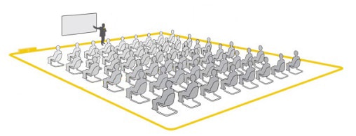
Perimeter Loop
The most basic design is a “Perimeter Loop”. As the name indicates, the wire is simply placed around the perimeter of the room.
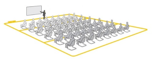
Snowman Loop
The next level design is called a “Snowman” or 3 Loop array. This involves laying wire around the perimeter of the room and then dividing the room into three equal thirds.
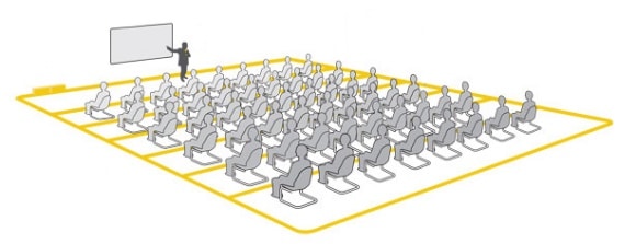
Phased Array Loop
The most advance design is called a “Phased Array”. This design involves installing wire around the perimeter of the room and then adding typically anywhere from three (3) to ten (10) or more wires across the width of the room.
Each of these designs have their advantages or disadvantages. The site survey results will help to determine what option(s) is feasible or which is not. The Complete Hearing Solutions representative can review the options at the completion of the site survey and provide a best practices recommendation.
Installation
Staff
The installation is done by our Installation Crew and supervised by a Project Manager. Each crew member has multiple years of Loop installation experience and a skill set that allows for the best possible outcome from the installation as far as aesthetics, properness, and completeness. Our crew are all employed directly for Complete Hearing. We do not use “subcontractors”.
Location Of Wire
Floor – the most common, for a few reasons:
- Can be tested before installation. Tests allow us to determine how a well the system will work if installed correctly.
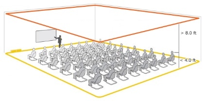
- The distance from the floor to the listeners ears is much less than from the ceiling to the user’s ears. Therefore, significantly less amps of output in order to get the volume to the appropriate level than a ceiling install will require. This results in less cost because less powerful amplifiers are required.
Ceiling – less common than floor installs
- Ceiling installs are used in locations in which it is not possible to place the wire on the floor.
- The wire can be placed above the ceiling, whether it is drywall or acoustical/drop/suspended.
- The majority of the time, a ceiling install will be done using a Phased Array design.
Techniques
For installs that are on the floor, rather than in the ceiling, there are 2 options:
- In the slab
- This is most commonly done during new construction after the slab is poured but before the floor finish is installed.
- Can also be done in existing space if floor finish is being replaced.
- Can be used under any type of flooring – carpet, carpet squares, hard wood, tile, and LVT (Luxury Vinyl Tile). However, this technique must be used when new tile or hardwood will be installed.
- We use electric wetsaws to keep the dust down and eliminates concerns about fumes from gas powered saw.
- The grooves will generally be approximately ¼” wide by ½” deep.
- Cuts are backfilled with a stucco/concrete mix.
- On the slab
- This can be done in existing space or new construction.
- Can be done under carpet, carpet squares, or LVT.
- Can be done in existing spaces or new construction.
Wire Type
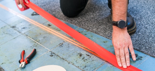
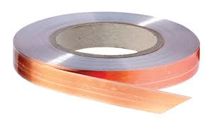
Flat copper foil wire
- Used for ON THE SLAB installs when the floor finish is or will be glue down carpet, carpet squares, or LVT/Vinyl tile planks.
- It is a ribbon-style copper wire and is ideal for use under these floor finishes as it reduces or eliminates the visibility of the wire.
- It is taped to the floor until the flooring is installed.
- It should be installed either the day of or at the most, a day or two prior to the flooring to limit the exposure to other trades and reducing the likelihood of damage.
Round wire
- Can be can be used in the ceiling or in direct burial situation.
- If in the ceiling, traditional THHN or Plenum rated wire will be used.
- If saw cut IN THE SLAB, special direct burial wire with a XLPE coating will be used to prevent corrosion due to alkalis in the concrete.
Note – if the flooring will be ceramic tile or exposed concrete, the wire MUST be placed in the slab.
As with all projects, Complete Hearing Solutions will visit the prospective venue and make recommendations on design, wire placement, and wire type.